Color Subsampling is a compression method that reduces the resolution of color data while retaining the brightness (luminance) data at full resolution.
It is widely used in video compression to reduce data size with minimal visual loss, as the human eye is more sensitive to brightness than color.
Types of Chroma Subsampling
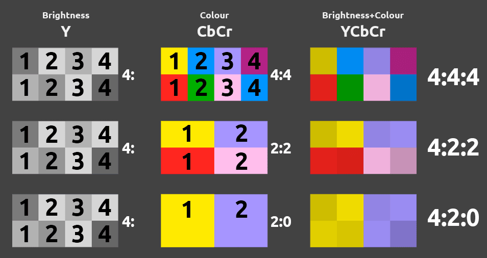
4:4:4 – No Subsampling
- In this format, both brightness (Y) and color channels (Cb and Cr) maintain full resolution, meaning each pixel has individual color and brightness data.
- This format offers the highest quality and is commonly used in professional editing and color correction.
4:2:2 – Horizontal Half Subsampling
- Here, color channels (Cb and Cr) are sampled at half the horizontal resolution, while brightness remains at full resolution.
- Commonly used for broadcasting and professional video as it provides high quality with moderate data reduction.
4:2:0 – Horizontal and Vertical Half Subsampling
- Color resolution is reduced both horizontally and vertically while brightness remains at full resolution.
- Widely used in consumer video formats such as Blu-ray and streaming, as it achieves significant data compression while preserving acceptable visual quality.
There is one more format: 4:1:1
It’s rarely used today but was once found in some professional formats like NTSC DV.
Naming
In chroma subsampling notation, such as 4:4:4, 4:2:2, and 4:2:0, each number represents how brightness and color data are recorded:
- The first digit is always “4” and indicates the sampling rate of luminance (brightness) horizontally, covering each pixel.
- The second digit shows the horizontal sampling of chrominance (color).
- The third digit indicates the vertical sampling of chrominance.
This subsampling reduces data size because human eyes are more sensitive to brightness than color, allowing for efficient compression without noticeable quality loss.
Comparison of formats
| Format | Brightness (Y) | Color (Cb and Cr) | Use Cases |
|---|---|---|---|
| 4:4:4 | Full | Full | High-quality editing and color correction |
| 4:2:2 | Full | Half horizontal | Broadcast and professional video |
| 4:2:0 | Full | Half horizontal and vertical | Consumer video, Blu-ray, streaming |
Each format caters to different needs, balancing quality and data efficiency based on the requirements of the specific video application.